![]() Return to Home -->
Modules -->
Fibre Channel Layers
Return to Home -->
Modules -->
Fibre Channel Layers
FC-1 Layer
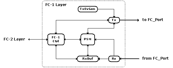
FC-1 handles 8B/10B encoding and 10B/8B decoding, monitors and manipulates port operational state, and responses to the link incidents. Six simple modules are implemented to realize these functionalities and they are: Port State Machine (PSM), FC-1 Controller (FC1Ctrl), Receiver Buffer (RxBuf), Receiver (Rx), Transmitter (Tx), and Transmitter Event Generator (TxEvGen). In fact, both Tx and Rx belong to FC-0, the physical layer, and for simplicity I merge FC-0 and FC-1 together.
![]() Mouse over the boxes to view specific modules.
Mouse over the boxes to view specific modules.

FC-1 Layer
Click here to see its VML version (requiring IE)
FC-FS defines nine FC_Port states: AC, LR1, LR2, LR3, LF1, LF2, OL1, OL2, and OL3, and five Primitive Sequences: LR, LRR, IDLES, OLS, and NOS used for the transition of port states. The transmission of the Primitive Sequences and the transition of the port states defined by FC-FS are implemented in the PSM module. Besides, PSM originates Port Initialization (including Port Speed Negotiation) and Link Initialization. As for the input events defined by FC-FS, I have implemented Rx/Tx Primitive Sequence, Loss-of-Signal (LOS), and Event time-out (R_T_TOV). Currently Loss-of-Sync and Link time-out (E_D_TOV) are not available.
A pass through layer for exchanging messages among the modules within FC-1, and between FC-1 and FC-2.
For the receiver buffer (implemented as a cQueue - see OMNeT++ User Manual for more about cQueue), once a Frame is received and popped out of the buffer queue, a request is issued either requesting the FC-2 Layer to receive and process the Frame at this local port (the destination port for the Frame) or requesting the Switch Control Centre to process and forward the Frame out onto an outgoing port (the intermediate port to relay the Frame to the destination port). The Frame destined to the local port is LOCAL_FRAME, and the one destined to the remote port is REMOTE_FRAME. SimSANs does not use a single packet to simulate the Fibre Channel Frame, instead one Frame is divided into three parts: Frame Head, Frame Payload, and Frame Tail - FC-2 module tells you more about the framing implementation. For LOCAL_FRAME, the request for processing the Frame cannot be issued to FC-2 Layer until all of the three parts arrive. For REMOTE_FRAME, the request for processing and forwarding the Frame can be issued to the Switch Control Centre right after the Frame Head arrives (the Frame Payload and Frame Tail may not in the receiver buffer at this moment).
For N_Port, all of the Class-3 Frames received with a valid N_Port Address_ID must be LOCAL_FRAME. N_Port cannot forward Frames. For F_Port and E_Port, all the Class-3 (for F_Port) or Class-F (for E_Port) Frames with a valid WKA (Well-Known Address) are considered to be LOCAL_FRAME. The WKAs used in SimSANs are: Fabric Controller (0xFFFFFD), Domain Controller (0xFFFC01 to 0xFFFCFE), Directory Server (0xFFFFFC), and F_Port (0xFFFFFE). The Class-3 Frames with an valid N_Port Address_ID received by F_Port or E_Port should be forwarded to a remote port, therefore, they must be REMOTE_FRAME. A Frame cannot be processed or forwarded must be discarded. For all FC_Ports, once the Frame Tail is popped out of the buffer queue, the R_RDY is issued to the attached port to free a BB_Credit.
10B/8B decoding the incoming messages including Frames, R_RDYs, and Primitive Sequences, etc and pushing the Frames into the Receiver Buffer. Notifying PSM of the LOS (Loss-of-Signal) or GOS (Gain-of-Signal) link events.
8B/10B encoding the outgoing messages and sending them out onto the link. Performing link speed negotiation with the attached port. Dynamically changing the link colour to reflect the link incident - black colour for active link and light gray colour for failed link. The Samples will show you more about how the link coloring works. Besides, for a given Host, Switch, or Device, when all of its active links fail, its icon will change reflecting it is into a DOWN state - How-To section tells more about this topic.
SimSANs uses transmitter ON (EV_TX_ON) or OFF (EV_TX_OFF) to simulate the link incident. In fact, link incident can be triggered by other events, say, fibre cut or Loss-of-Sync, etc. but in the SimSANs, TxEvGen is the only source to trigger the link incident. Note from the perspective of Receiver, the events EV_TX_ON and EV_TX_OFF will be observed as Gain-of-Signal (GOS) and Loss-of-Signal (LOS).
This page was last updated 2003.10.15