![]() Return to Home -->
Modules -->
Device - Disk Array
Return to Home -->
Modules -->
Device - Disk Array
ACP Module
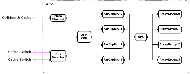
ACP module contains an ACP CPU, an ACP Peripheral Bus Controller (APC), several Array Groups and their associated Array Group Drivers, a Meta Channel, and a Bus Selector. The functions of Meta Channel and Bus Selector are same as those in CHIP, with Meta Channel used to exchange control information with Control Memory and Cache (CtrlMemCch), and Bus Selector used to exchange data information with CtrlMemCch through Cache Switches. In current SimSANs version, both ACP CPU and Array Group Drivers are just pass-through layers. ACP Peripheral Bus Controller functions no difference from CHIP CPC or Host HPC. The ACP module's core component is Array Group, which handles physical block IO requests and performs disk accesses. Following figure shows an example ACP module with four Array Groups installed and two Cache Switches connected.
![]() Mouse over the boxes to view specific modules.
Mouse over the boxes to view specific modules.

ACP Module
Click here to see its VML version (requiring IE)
Array Group module contains a number of Disk Drives, each of which is connected to a FC-AL Hub port. Although the hub network appears to be a star topology, internally the disk drives and hub form a unidirectional loop. Following figure shows the module structure and its logical topology.
![]() Mouse over the boxes to view specific modules.
Mouse over the boxes to view specific modules.

Array Group Module and the Logical Topology
Click here to see its VML version (requiring IE)
Several topics need to be mentioned regarding the implementation this module: Sector IO and IO Request Transformations, Loop Arbitration, and Task Management.
IO Request Transformations: When a physical block IO request comes, it will be segmented into multiple contiguous Sector IO requests, which then be issued to proper disks for media accesses - note sector is the basic unit of accessing disk media. If you happen to travel through the whole IO path designed in the SimSANs, you may find several different IO definitions - SCSI IO, SUB IO in Host SCSI Layer, FCP IO in SCSI_FCP Layer, LUN IO in LUN Controller, Block IO and Physical Block IO in CtrlMemCch, and here Sector IO in Array Group. So many "IO" terms may get you confused so it is time to clear the picture about how they are related - see the following diagram:

IO Request Transformations
Click here to see its VML version (requiring IE)
Basically the IO request transformation works in this way: Host IO Generator generates SCSI IO request, which then be segmented into single-DATA_Action SUB IO requests; SUB IO is encapsulated into FCP IU and transmitted through Fibre Channel Layers to CHIP, where the FCP IO is forwarded to LUN Controller and transformed into LUN IO request; LUN IO request is segmented into LUN Block IO requests for Caching operations; For those Cache-missed block requests, they will be transmitted to Array Group as Physical LUN Block IO requests; At Array Group, physical block IO request is segmented into Sector IO requests for disk media accesses. Note there's no much difference between SUB IO and LUN IO except that SUB IO is the FCP IO at Initiator side while LUN IO is the FCP IO at Target side.
Loop Arbitration: As mentioned before, a unidirectional loop topology is formed by connecting the outgoing port of one disk to the incoming port of the next. The FC-AL HUB module implements a simplified version of FC-AL loop arbitration mechanism. The general picture of arbitration mechanism is:
Step 1: A single port arbitrates for usage of the entire
loop.
Step 2: Once it obtains loop access, it opens up
communications with another port on the loop.
Step 3: The source port transmits Fibre Channel traffic at
the full guaranteed link bandwidth (1Gbps or 2Gbps).
Step 4: When data transfer is done, the source port releases
the loop for usage by another port.
Step 5: During communications between two ports on the loop,
the non-participating ports forward the data around the loop,
monitoring the traffic to watch for the next chance to communicate
but not interfering in the current transmission.
Task Management: FC-AL HUB uses a sector request queue to hold all the IO requests that are still waiting for the loop privilege. Without gaining a privilege to access the loop, a sector IO request cannot be popped out from the queue. Besides, a buffer monitor is setup to track each disk's buffer utilization. If a disk's buffer is full then FC-AL HUB should not transmit more sector IO requests to that disk even the loop access is obtained - in this case, the loop access privilege will be given to the next request waiting in the queue. As a matter of fact, the buffer monitoring should be performed by Array Group Driver (currently just a pass-through layer) by using some sort of SCSI task management functions, however, I have simplified its implementation and moved this function into FC-AL HUB. Future versions may consider more on this topic.
Disk drive module has been re-designed in version 2.0. Several topics are involved for modeling disk drive and simulating its behavior: Disk Drive Parameters, Logical to Physical Sector Mapping, Buffer and Command Queuing, and Disk Media Access.
Disk Drive Parameters: Parameter number has been expanded from 8 of version 1.0 to 17 as shown in the list below:
|
Parameter Name |
Compatibility |
|
Number of Cylinders |
version 1 and 2 |
|
Sector Size |
version 2 only |
|
Average Sector Density |
version 1 and 2 |
|
Number of Bands |
version 2 only |
|
CPB Index |
version 2 only |
|
SPB Index |
version 2 only |
|
Logical to Physical Sector Mapping Flag |
version 2 only |
|
Number of Heads |
version 1 and 2 |
|
Rotation Speed |
version 1 and 2 |
|
Buffer Size |
version 2 only |
|
Additional Write Delay |
version 1 and 2 |
|
Head Switch Delay |
version 1 and 2 |
|
Cylinder Switch Delay |
version 1 and 2 |
|
Controller Overhead |
version 1 and 2 |
|
FC-AL Delay |
version 2 only |
|
Command Queue Depth |
version 2 only |
|
Command Queuing Delay |
version 2 only |
Most of the 17 parameters are quite straight-forward so user should have no much difficulties understanding them. System Configuration has more details about how to configure these parameters. Here I only focus on talking about Disk Band and three relevant parameters (NUM_OF_BAND, CPB_INDEX, and SPB_INDEX) implemented in SimSANs. In version 1.0, the sector density (sectors per track) is setup as a straight value for the whole disk, which proves to be less accurate in disk drive simulation because for a disk platter tracks at outer area are longer than those at inner area. To maximum storage capacity the sector density of a track should be linear scaled with the track's length, i.e., outer tracks should store more data than inner tracks. Disk Band is used to achieve this purpose by zoning adjacent tracks together and dividing the platter into multiple bands, with the outer bands grouping more tracks and having larger sector density.
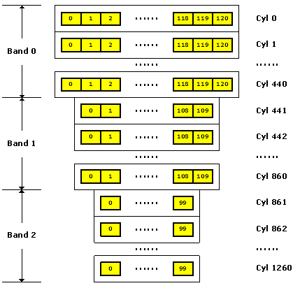
In SimSANs, adjacent bands have different number of tracks, and all the tracks in a band have the same sector density. The parameters CPB_INDEX and SPB_INDEX are used to define the linear scales of cylinder (or track) number and sector density between adjacent bands. The usage of these two parameters is illustrated as follows given NUM_OF_BAND = 3, NUM_OF_CYL = 1261, CPB_INDEX = 0.05, and SPB_INDEX = 0.1:

Disk Band Example
Click here to see its VML version (requiring IE)
Where the yellow color box represents the
Sector, and the number in the box denotes its
Sector_ID on the track. From this
example we can get:
[1] Band0_cylNum = Band1_cylNum x (CPB_INDEX + 1) <--> 441 = 420 x
1.05
[2] Band1_cylNum = Band2_cylNum x (CPB_INDEX + 1) <--> 420 = 400 x
1.05
[3] Band0_trkSec = Band1_trkSec x (SPB_INDEX + 1) <--> 121 = 110 x
1.1
[4] Band1_trkSec = Band2_trkSec x (SPB_INDEX + 1) <--> 110 = 100 x
1.1
Note Bandx_cylNum
stands for cylinder number for band x
(x>=0) and Bandx_trkSec
stands for sector density (sectors per track) for band
x (x>=0). It is obvious to
conclude that
Bandx+1_cylNum = Bandx_cylNum
x (CPB_INDEX + 1)
Bandx+1_trkSec = Bandx_trkSec
x (SPB_INDEX + 1)
Besides the above parameters, another very important disk parameter is seek delay table, which contains the entries of the seek delay against a given cylinders-to-move. SimSANs has provided several pre-designed disk models. Please check these disk models and their parameters in System Configuration.
Logical to Physical Sector Mapping: The sector IO issued from FC-AL is logical sector (see IO Request Transformations mentioned in FC-AL Module) which must be mapped to the correspondent physical sector before media access. In SimSANs, the layout of physical sectors is on cylinder basis, i.e., sector is numbered cylinder by cylinder. Logical sector layout can be either on cylinder basis or on cylinder-band basis, i.e., sector numbering starts from the 1st band of the 1st head to the 1st band of the last head, then the 2nd band of the 1st head to the 2nd band of the last head, until finally the last band of the 1st head to the last band of the last head. The following diagram shows the difference between cylinder and cylinder-band:

Cylinder and Cylinder-Band
Click here to see its VML version (requiring IE)
The parameter Logical to Physical Sector Mapping Flag mentioned before is used to customize the logical sector layout. Besides, user can choose whether or not output the logical sector map files - map file may be as large as several mega bytes. Two map files can be generated for a given disk model, one with the suffix of "LogSecMap_1" when cylinder-band based layout is selected, and the other with the suffix of "LogSecMap_0" when cylinder based layout is selected. Note cylinder based logical sector layout is consistent with physical sector layout.
Buffer and Command Queuing: Disk buffer includes an Input Buffer and an Output Buffer. Input Buffer stores the sector requests waiting for media access while Output buffer stores the sector data or completion notifications waiting for FC-AL loop access privilege. Output Buffer is a simple FIFO queue. The transfer of the output data involves an loop arbitration mechanism (see more information in FC-AL HUB module). Input Buffer is much more complex than Output Buffer since command queuing mechanism occupies Input Buffer space. In SimSANs, Input Buffer is composed of three parts: Input Queue, Command Queue, and Access Queue. Following diagram shows their relationship.

Command Queuing
Click here to see its VML version (requiring IE)
- Access Queue is the buffer in which the sector requests are waiting for media accesses. All requests in Access Queue belong to a request group. The whole group of requests must be fulfilled before any other requests can be pushed in, i.e., Command Queue cannot send in more requests until Access Queue is emptied.
- When disk media is busy Command Queue can keep taking in requests
from Input Queue until the Command Queue
Depth (one of the 17 disk parameters) is reached.
- All the requests within Command Queue are sorted in sector
ascending order from head to tail, i.e., from right most to left
most in the above figure.
Modern disks normally have implemented cache mechanism especially the Read Ahead cache to boost performance for sequential access. SimSANs current version doesn’t implement any disk cache mechanism since Read Ahead cache may degrade the performance of random access like online transaction application. Future version may consider modeling disk cache.
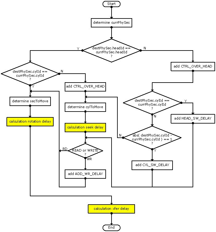
Disk Media Access: The most important disk operation is the media access. Modeling the response time of media access should be as accurate as possible since media access delay usually counts for the most part of the whole IO response time – generally disk media accessing is the performance bottleneck throughout the whole IO path. The most important delays are: seek delay, rotational delay, and transfer delay. Besides, controller overhead, additional write delay, head switch, and cylinder switch should also be taken into account. Some revisions have been made over version 1.0 to improve the accuracy of simulating media access. The following flowchart shows the media access procedure.
Parameter List for Disk Media Access
|
Parameter Name |
Description |
Attribute |
|
currPhySec |
current physical sector pointed by the active read/write head |
working |
|
destPhySec |
destination physical sector to be accessed |
input |
|
x.headId |
Head_ID of the physical sector x |
working |
|
x.cylId |
Cylinder_ID of the physical sector x |
working |
|
CTRL_OVER_HEAD |
controller overhead to initiate mechanic of read/write head |
input |
|
HEAD_SW_DELAY |
delay for performing head switch operation |
input |
|
CYL_SW_DELAY |
delay for performing cylinder switch operation |
input |
|
ADD_WR_DEALY |
additional delay for settling read/write head for write operation |
input |
|
secToMove |
sectors to move before reaching the destination sector on the track |
working |
|
cylToMove |
cylinders to move before reaching the destination cylinder |
working |

Disk Media Access Flow-Chart
Click here to see its VML version (requiring IE)
This page was last updated 2003.10.15